
Why a Floor Type Boring Mill Wins on Oversized Parts
A floor type boring mill is the right choice when your parts are too large, heavy, or awkward for a conventional machine table. Its moving column travels along fixed floor plates while the workpiece stays in place. This gives manufacturers long-axis reach, strong support for heavy cuts, and more freedom to fixture very large castings, weldments, housings, and structural parts.
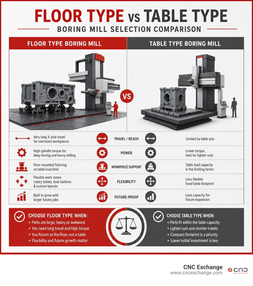
Compared with a table-type boring mill, choose a floor-type design when you need:
- Very long X-axis travel for oversized workpieces
- High spindle torque for deep boring and heavy milling
- Floor-mounted fixturing instead of a table with a fixed load limit
- Flexible work zones, including rotary tables or dual stations
- A machine that can grow with larger future jobs
These machines are common in energy, shipbuilding, mining, aerospace, oil and gas, and heavy equipment work. Depending on configuration, they can machine parts weighing well above 100 tons and support travels measured in meters rather than inches. The tradeoff is a larger footprint and a more demanding installation, so machine selection should begin with part size, weight, required bore depth, and the shop's crane and foundation capacity.
I'm Jared Gray, with more than 12 years of experience buying, selling, and brokering CNC chip-making equipment, including large-format floor type boring mill configurations. I help manufacturers evaluate equipment based on real production needs, from machine capability and condition to installation, resale value, and long-term fit.
Anatomy and Architecture of a Floor Type Boring Mill
The core design principle of this machinery centers on separating the cutting mechanism from the workpiece support structure. In standard machining centers, the workpiece moves beneath or alongside a stationary column. On a floor-type system, the workpiece rests securely on massive, stationary floor plates while the column itself glides smoothly along an independent runway.
Massive cast-iron components—predominantly high-grade Meehanite castings—form the base runway, the moving column, the headstock housing, and the extending ram. This heavy cast-iron construction delivers superior vibration damping and structural stiffness, which are critical when running high-horsepower cuts meters above floor level. The dynamic stability of the structure ensures that cutting forces do not deflect the tool path, even during aggressive material removal on hardened alloys.
Moving Column vs Stationary Bed Mechanics
In moving-column architecture, the X-axis longitudinal traverse is achieved entirely by moving the entire vertical column assembly along the foundation runway. Because the machine bed does not carry the weight of the workpiece, X-axis travel can be engineered to incredible lengths—often extending from 4,000 mm to well over 40,000 mm.
The stationary floor plates are anchored directly into a dedicated, reinforced concrete foundation. This structural isolation prevents the massive weight of a 50-ton or 100-ton part from creating localized deflection in the machine’s guideways. By decoupling the static workpiece load from the dynamic axes of the machine, geometric precision remains completely uncompromised regardless of workpiece mass.
Spindle Power, Ram Travel, and Multi-Axis Motion
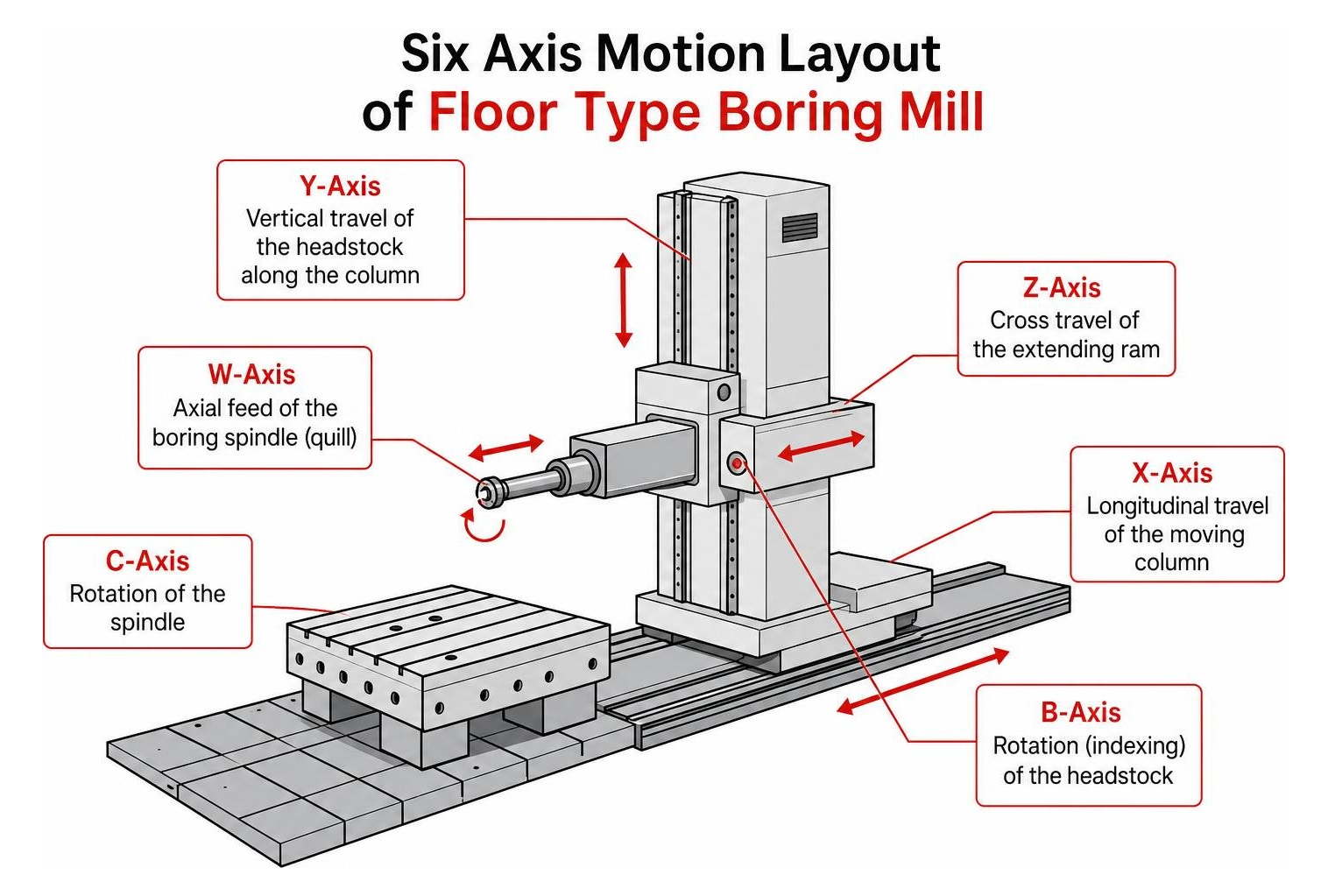
The cutting head of a floor-type mill is an engineering marvel designed for heavy roughing and deep-reach precision. Machining envelopes are defined by multi-axis coordination:
- X-Axis: Longitudinal travel of the moving column.
- Y-Axis: Vertical travel of the headstock along the column (often up to 7,000 mm).
- Z-Axis: Cross travel of the extending rectangular ram (typically 1,200 mm to 1,600 mm).
- W-Axis: Axial feed of the extending boring spindle (quill) housed inside the ram.
Spindle diameters typically range from Ø130 mm up to Ø260 mm, powered by robust spindle motors delivering anywhere from 30 kW to over 110 kW and paired with multi-speed, high-torque gearboxes. Heavy-duty platforms like the Skoda Machine Tool WD250 Horizontal Boring Mills illustrate how massive ram and quill extensions enable deep internal boring within colossal turbine casings and engine blocks without sacrificing axial rigidity.
Floor-Type vs Table-Type Boring Mills: Key Differences
Selecting the right machine format comes down to part geometry, mass, and workflow dynamics. The table below outlines how these structural philosophies contrast in daily production:
| Feature / Metric | Table-Type Boring Mill | Floor-Type Boring Mill |
|---|---|---|
| Workpiece Placement | Moving machine table (cross/longitudinal) | Stationary floor plates / independent base |
| Workpiece Weight Limit | Limited (typically 5 to 25 tons) | Virtually unlimited (exceeding 100+ tons) |
| X-Axis Travel | Restricted by machine bed (usually < 4,000 mm) | Modular & extendable (4,000 mm to 40,000+ mm) |
| Foundation Needs | Standard industrial floor or simple pit | Deep-engineered reinforced concrete foundation |
| Workstation Flexibility | Single setup envelope | Multi-station, pendulum, and rotary integration |
| Primary Use Case | Medium-to-large prismatic components | Oversized, heavy, long, or awkward structures |
Machine Structural Rigidity and Workpiece Weight Capacities
While horizontal table-type boring mills excel at machining medium-to-large prismatic parts where the table can smoothly translate the part along linear axes, they hit a physical threshold when parts become excessively heavy. When a 30-ton casting is placed on a moving table, inertia during direction reversals can cause table sag, slide wear, and micro-deflections that degrade surface finishes.
Floor-type machines completely eliminate table weight restrictions. Because the component sits on heavy cast-iron T-slotted floor plates anchored into bedrock-grade concrete, you can load extreme workpieces with zero structural impact on machine geometry. This architecture allows for maximum stock removal rates, aggressive feeds, and high-torque face milling on parts that would overwhelm standard table mechanisms.
Footprint, Foundation Costs, and Setup Versatility
Floor-type mills require significant floor space and deep-pit foundations designed to isolate dynamic cutting vibrations from surrounding plant equipment. The engineering of these reinforced foundations represents a notable upfront capital expense.
However, the payoff is unparalleled setup versatility. The low-profile floor plates offer superior crane accessibility, allowing overhead gantry cranes to drop massive components directly onto fixturing locations without clearing tall machine enclosures. Operators gain clear, safe access around all sides of the workpiece for measuring, setting up angle plates, and adjusting custom clamping systems.
Critical Technical Specifications to Evaluate When Buying
When sourcing a floor-type boring mill, evaluating core specifications ensures the machine matches your shop's component complexity and duty cycle:
- Spindle Motor Power & Torque: Motor ratings from 30 kW to 110 kW, with multi-range gearboxes producing torque values exceeding 1,500 to 3,000 Nm for heavy boring cuts.
- Axis Travels and Feed Rates: Rapid traverse speeds up to 35,000 mm/min with acceleration rates between 1.0 and 1.5 m/s² ensure rapid repositioning over long X-axis beds.
- Ram Section Dimensions: Heavy ram profiles (such as 560 x 515 mm) provide superior structural resistance against bending moments when extended deep into a bore.
- Thermal Compensation: Advanced real-time sensor networks that monitor ambient, column, and spindle temperatures to adjust kinematic offsets dynamically.
- Positioning Accuracy: High-grade optical linear scales delivering positioning accuracy within 0.02 mm per 1,000 mm of travel.
Hydrostatic vs Linear Guideways in a Floor Type Boring Mill
The choice of guideway technology plays a vital role in long-term machine performance and structural life.
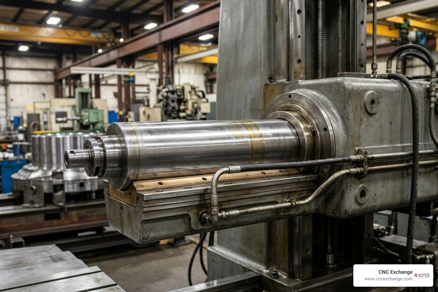
Linear roller guideways provide cost-effective motion, high rapid-traverse dynamics, and straightforward field replacement. They are well-suited for high-speed milling and general fabrication environments.
In contrast, full hydrostatic guidance utilizes a pressurized continuous oil film (typically around 0.02 mm thick) between moving surfaces, completely eliminating metal-to-metal contact. This ensures zero mechanical guideway wear, exceptional vibration damping during aggressive roughing, and lifetime accuracy retention (often maintaining ±0.001 mm positioning repeatability over decades). Heavy-duty machines built for deep stock removal, such as the Dorries Scharmann Heavy Cut 1 Horizontal Boring Mills, demonstrate how hydrostatic systems absorb severe cutting forces and eliminate stick-slip friction.
Advanced Spindle Configurations and Tool Management Systems
Modern floor mills feature versatile spindle configurations, combining direct-drive high-speed milling spindles (up to 7,000 RPM) with geared quills for low-end roughing torque.
To maximize operational versatility, leading manufacturers integrate automatic head changers (AEC) that swap between straight horizontal spindles, universal 5-axis heads, and orthogonal milling heads in minutes. Automatic tool changers (ATC) with chain or rack-style magazines holding 40 to 120+ tools ensure that complete drilling, tapping, profiling, and finishing sequences occur in a single unattended cycle. High-pressure internal coolant delivery (often up to 70 bar) flushes deep cavities, prevents thermal growth, and extends cutting tool life.
Custom Configurations and Advanced Multitasking Capabilities
A major strength of the floor-type platform is modular customization. Typical configurations include:
- Multi-station floor plates arranged along extended runway beds
- Integrated CNC rotary tables (B-axis) for indexing and continuous contouring
- Auxiliary sliding tables (V-axis) for secondary positioning
- Automatic universal indexing heads (stepped or continuous 5-axis)
- Angle plates, tombstone fixtures, and modular clamping towers
- Enclosed operator cabins that travel vertically and horizontally with the headstock
- Chip conveyor systems running the full length of the X-axis bed
Pendulum Machining and Independent Workstations
Pendulum machining divides an extended X-axis bed into two or more independent work envelopes. While the spindle performs active cutting operations on Workstation A, operators safely fixture, indicate, and prepare a new workpiece on Workstation B.
This arrangement virtually eliminates setup downtime. The spindle transitions seamlessly between stations, maximizing chip-to-chip uptime and dramatically lowering the cost-per-part on mid-to-high-volume heavy component runs.
Integrating Rotary Tables and Robotic Tool Changers on a Floor Type Boring Mill
Adding a heavy-duty B-axis CNC rotary table transforms a standard 3-axis or 4-axis mill into a versatile multi-sided production center. When mounted on a sliding V-axis base, the rotary table can move closer to or further from the column, providing flexible positioning for workpieces of varying diameters.
Integrating a robotic tool changer expands tool capacity to hundreds of pockets. This setup enables single-setup machining on intricate components like pump housings or gearboxes, where drilling, fine boring, face milling, and thread tapping across multiple faces can be completed without manual repositioning.
Key Industrial Applications and Long-Term Value Retention
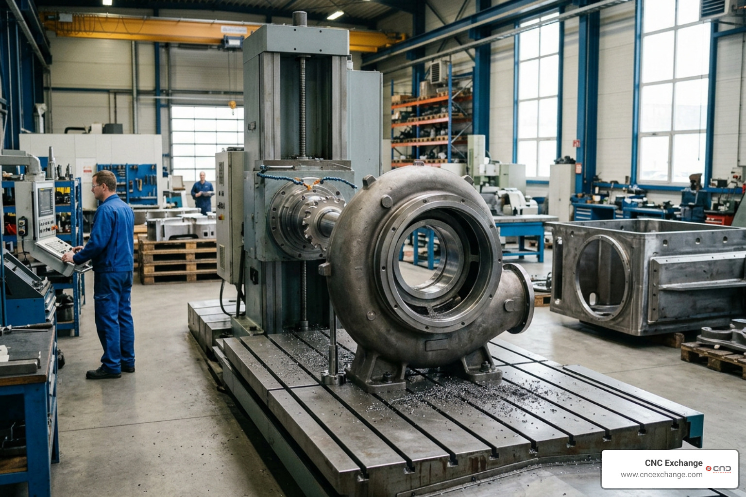
Floor-type boring mills represent significant capital equipment investments, but their robust design and structural longevity deliver enduring value. Built with rigid cast beds, these machines retain their dimensional accuracy and high market value across decades of demanding industrial service.
Heavy Industry Use Cases: Energy, Aerospace, and Shipbuilding
- Energy & Power Generation: Deep boring and precision facing of gas and steam turbine housings, generator rotors, wind turbine blade hubs, and nuclear reactor pressure vessels.
- Shipbuilding & Marine: Machining massive diesel engine crankcases, propeller shaft struts, rudder horns, and structural hull sections.
- Aerospace & Defense: Milling oversized airframe assembly tooling, rocket engine mounting rings, armored vehicle hull structures, and launcher bases.
- Mining & Heavy Construction: Line-boring boom arms, excavator frames, rock-crushing chassis, and large-diameter conveyor drive housings.
Total Cost of Ownership and Lifecycle Maintenance
Optimizing the Total Cost of Ownership (TCO) for a floor-type mill requires consistent preventive maintenance:
- Lubrication Management: Regularly checking hydrostatic oil viscosity, particulate filtration, and linear rail auto-lube reservoirs.
- Thermal Stabilization: Ensuring chiller units and thermal compensation sensors operate correctly to prevent spindle growth during long cycle times.
- Kinematic & Laser Calibration: Periodically recalibrating multi-axis squareness, pitch, and yaw using laser interferometers.
- Chip & Coolant Filtration: Keeping high-volume chip flumes clear to prevent heat transfer into the foundation bed.
Properly maintained floor-type boring mills suffer minimal structural wear, ensuring high asset depreciation resistance and strong resale value on the secondary machinery market.
Frequently Asked Questions About Boring Mills
What is the primary difference between floor-type and table-type boring mills?
The key difference lies in whether the workpiece moves. In a table-type machine, the workpiece is clamped to a table that moves along linear axes during cutting. In a floor-type boring mill, the workpiece remains stationary on heavy floor plates while the column moves along the X-axis runway. This enables floor-type machines to support virtually unlimited workpiece weights and extended travel lengths.
What load capacities can floor-type boring machines support?
Because the workpiece sits on independent floor plates supported directly by a dedicated concrete foundation, load capacity is virtually unlimited. Standard installations routinely handle workpieces weighing from 20 tons to well over 100 tons, limited only by your facility's overhead crane and foundation load ratings.
Why is hydrostatic guidance preferred for large-scale boring operations?
Hydrostatic guideways utilize a continuous pressurized oil film that completely separates moving surfaces. This eliminates metal-to-metal contact, preventing mechanical wear and ensuring zero stick-slip during micro-feed adjustments. Hydrostatic systems also provide exceptional vibration damping during heavy roughing cuts, significantly improving tool life and surface finish.
Conclusion
A floor type boring mill provides the rigidity, long-axis travel, and structural independence needed to machine the world's largest industrial components. Whether handling massive energy-sector castings, heavy defense fabrications, or multi-station pendulum setups, these machines deliver unmatched stock removal rates and tight tolerances on oversized parts.
When you are ready to evaluate, acquire, or upgrade your facility's heavy chip-making capabilities, explore our extensive inventory of heavy-duty horizontal boring mills at CNC Exchange to find the right equipment for your production demands.