
CNC Router Wood Cutting Starts With Control, Not Guesswork
CNC router wood cutting is the process of using a computer-guided spindle and cutting bit to shape wood accurately and repeatably. For clean results, start with the right bit, secure the material, set a conservative feed rate and depth of cut, then test the toolpath on scrap before running production parts.
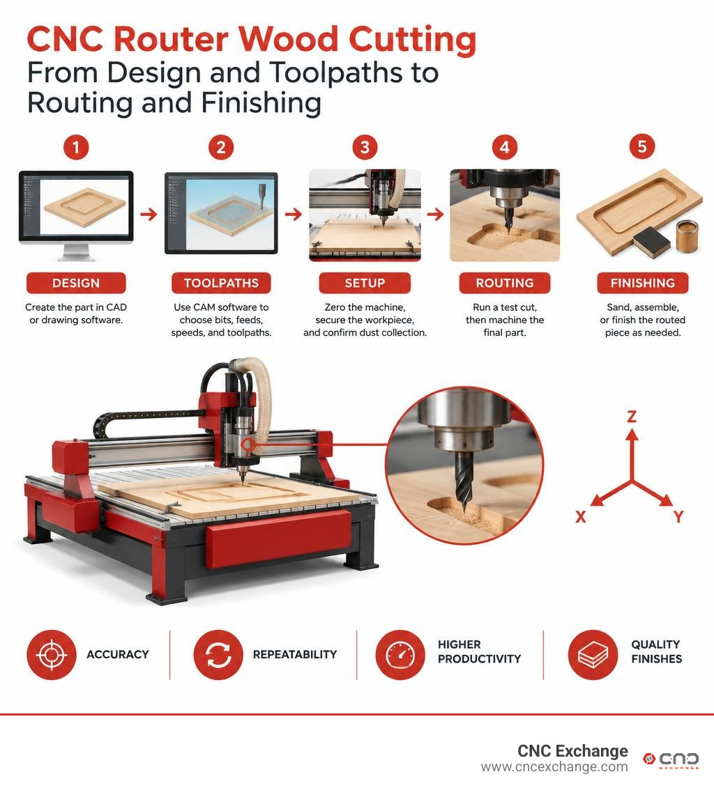
A reliable workflow looks like this:
- Create the part in CAD or drawing software.
- Use CAM software to choose bits, feeds, speeds, and toolpaths.
- Zero the machine, secure the workpiece, and confirm dust collection.
- Run a test cut, then machine the final part.
- Sand, assemble, or finish the routed piece as needed.
This approach turns repeat jobs such as cabinet parts, signs, furniture joinery, panels, and custom components into a repeatable process. The machine matters, but so do rigidity, spindle power, ball-screw or lead-screw condition, proper workholding, and a clean cutting area. A desktop router can suit prototypes and short runs, while a larger industrial machine can improve throughput, hold larger sheets, and reduce labor in a production shop.
I am Jared Gray, with more than 12 years of experience sourcing, selling, and evaluating CNC chip-making equipment for shops around the world. In this guide, I will break down CNC router wood cutting techniques that help makers and manufacturers improve cut quality, production speed, and equipment decisions. For a broader look at the process, the CNC router entry on Wikipedia explains the machine types and common applications behind these workflows.
Fundamentals of CNC Router Wood Cutting: Mechanics, Drives, and Setup
Every precise wood cut starts with a mechanically sound machine. If a gantry flexes by half a millimeter or the frame absorbs cutting forces unevenly, no amount of software adjustment can fix the resulting chatter, oval holes, or scalloped edges. A CNC router operates across three primary Cartesian axes (X, Y, and Z), where stepping motors turn drive mechanisms to move the cutting head along linear rails.
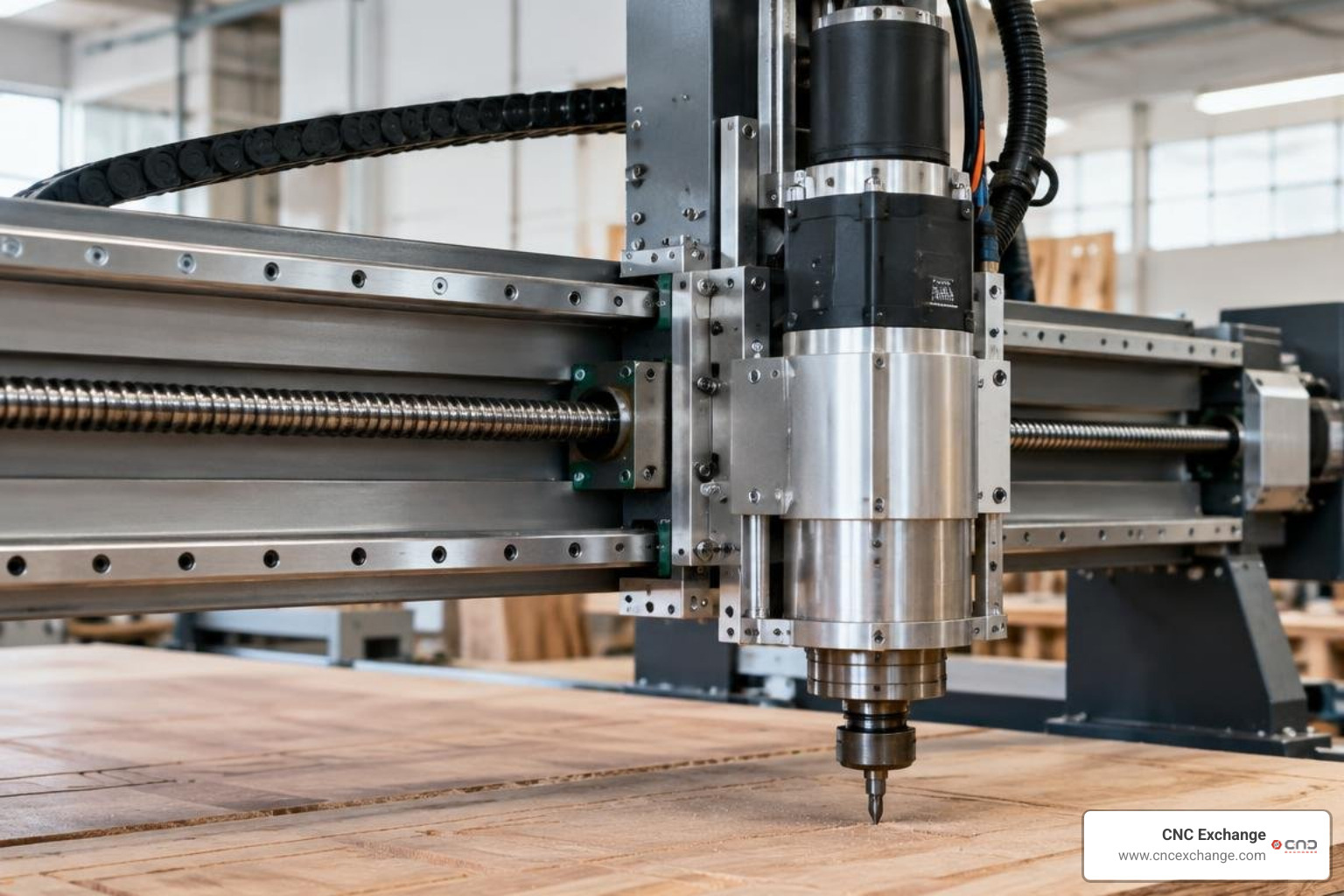
When setting up a router, initial mechanical calibration is critical:
- Perpendicular Squaring: Ensure the gantry sits at a perfect 90-degree angle to the Y-axis rails. Dual-motor Y-axes must use independent homing switches to auto-square on startup.
- Axis Tramming: Mount the spindle perpendicular to the bed. A tilted spindle creates stepped floors in flat pockets.
- Z-Axis Calibration: Use a conductive touch plate or electronic Z-probe to set your tool zero surface consistently.
- Linear Rail Lubrication: Clean and grease profile rails to stop micro-stuttering during low-speed feed moves.
| Drive Feature | Lead Screw Drives | Ball Screw Drives |
|---|---|---|
| Friction Level | Moderate to High (Sliding Contact) | Minimal (Rolling Contact) |
| Backlash Profile | Requires anti-backlash nuts; wears over time | Near-zero backlash via preloaded bearings |
| Positioning Accuracy | Typically ±0.1 mm to ±0.2 mm | Typically ±0.03 mm to ±0.05 mm |
| Feed Rate Ceiling | Moderate (Whipping at higher RPMs) | High (Maintains stability at high speeds) |
| Maintenance | Frequent cleaning; nut block replacement | Periodic greasing of bearing raceways |
Core Components: Drive Systems, Ball Screws vs. Lead Screws, and Rigidity
The mechanical drive directly determines how smoothly your machine cuts under load. While entry-level routers frequently rely on lead screws with spring-loaded brass or Delrin anti-backlash nuts, precision desktop setups and production platforms utilize hardened ball screws. Ball screws substitute sliding friction with recirculating ball bearings, providing exceptional mechanical efficiency, reduced heat generation, and positioning repeatability down to ±0.02 mm.
Frame dampening is equally vital. High-frequency spindle vibration combined with the natural resistance of dense timber can introduce deflection. A robust framework paired with supported linear guide rails and high-torque NEMA stepper motors or closed-loop hybrid servos prevents lost steps during aggressive plunge operations. For commercial projects requiring tight tolerances—such as architectural milling, intricate fretwork, and detailed signage—high-rigidity frames paired with zero-backlash ball screws ensure clean, crisp profiles every time.
Desktop vs. Industrial Routing Platforms
Selecting the right platform depends on your production scale, cycle times, and sheet capacities:
- Desktop & Benchtop Routers: Units ranging from 600 x 500 mm up to 1000 x 1000 mm work areas handle smaller components, guitar bodies, joinery prototypes, and artistic reliefs. They draw modest power, use air-cooled or light water-cooled spindles, and fit into standard makerspaces.
- Mid-Range Commercial Routers: Platforms featuring 4 x 4 ft or 4 x 8 ft beds bridge the gap, enabling full-sheet processing with higher-power spindles (2.2 kW to 9 kW) and faster rapid travel speeds.
- Heavy Industrial CNC Machining Centers: When high-volume cabinet production, 24/7 nesting operations, and high feed rates are required, heavy industrial machines are the standard. Facilities tackling nested-base manufacturing rely on heavy-duty production machinery like the Komo Fusion VR512 CNC machining center or the high-production Thermwood CS45 CNC router. These systems feature heavy steel weldment bases, multi-zone vacuum tables, automatic tool changers (ATC), and high-output vacuum pumps that streamline full-sheet panel processing.
Essential CNC Router Wood Cutting Techniques and Parameters
Achieving clean edge finishes in natural timber and composite sheet goods requires dialing in feeds, speeds, and cutting strategies. Wood is an anisotropic material—meaning its grain structure, hardness, and moisture content vary across the board.
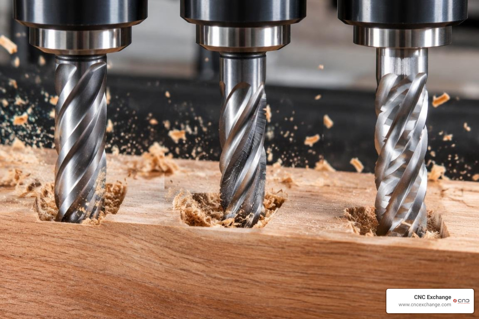
If your chipload is too small, your bit rubs rather than cuts, generating heat, dulling the carbide edge, and burning the timber. If the chipload is too large, you risk severe tool deflection, step loss, and ragged edge tear-out.
Mastering Feeds, Speeds, and Spindle RPM for CNC Router Wood Cutting
Spindle speeds on modern CNC routers generally range between 8,000 and 30,000 RPM. Match your RPM to your feed rate to keep chips moving out of the cut zone:
- Feed Rates: Modern rigid routers can cut softwoods and composites at feed rates ranging from 2,500 mm/min to over 8,000 mm/min depending on bit diameter and spindle horsepower.
- Heat Management: Chips carry heat away from the workpiece. If the waste coming off your cutter is fine powder rather than distinct wood chips, increase your feed rate or lower your spindle RPM.
- Climb vs. Conventional Milling: Climb milling (where the cutter rotates with the direction of feed) typically yields cleaner edge finishes on solid hardwoods and minimizes grain tear-out. Conventional milling (feeding against the tool rotation) provides greater stability on lighter, less rigid desktop routers susceptible to tool deflection.
- Spindle Duty Cycles: Heavy production models, including a CR Onsrud heavy-duty wood router, utilize heavy industrial spindles rated to sustain high-torque cutting parameters through multi-shift manufacturing cycles without thermal throttling.
Advanced Toolpath Strategies: Nesting, Pocketing, and 4th Axis Rotary Carving
Modern CAM suites allow woodworkers to use advanced toolpath strategies that minimize tool wear and maximize yield:
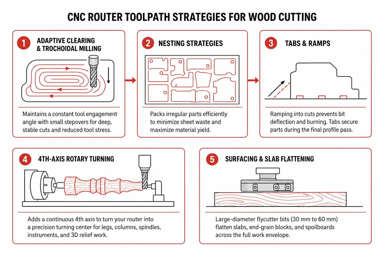
- Adaptive Clearing and Trochoidal Milling: Instead of plowing an endmill into a deep slot at full width, adaptive toolpaths maintain a constant tool engagement angle, cutting deep with small stepovers to prevent bit breakage.
- Nesting Strategies: High-efficiency nesting algorithms pack irregular components closely together on full sheets. Industrial wood shops regularly employ dedicated nesting centers, such as the Weeke Optimat NBP084 nesting platform, to minimize sheet scrap in flat-panel cabinetry.
- Tabs and Ramps: Ramping into profiles prevents bit deflection and burning caused by direct vertical plunges. Holding tabs keep cut parts from vibrating loose and hitting the spinning bit during the final profile pass.
- 4th-Axis Rotary Turning: Adding a continuous 4th axis turns your flatbed router into a precision turning center for table legs, architectural columns, musical instruments, and complex 3D relief sculptures.
- Surfacing and Slab Flattening: Using large-diameter flycutter bits (30 mm to 60 mm diameter) allows you to flatten live-edge timber slabs, end-grain butcher blocks, and MDF spoilboards across the entire work envelope.
Material Selection, Tooling, and Workholding for Flawless Cuts
Different woods behave in distinct ways under a router bit. Selecting the right cutting geometry and securing your workpiece firmly prevents chatter marks and part movement.
Hardwoods, Softwoods, Sheet Goods, and Hybrid Non-Ferrous Milling
- Solid Hardwoods (Oak, Maple, Walnut, Cherry): Dense grain structures demand rigid setups and sharp carbide tooling. Cut climb toolpaths to prevent edge tear-out on cross-grain cuts, and use moderate stepdowns.
- Softwoods (Pine, Cedar, Fir): Softer fibers tend to crush or fuzz if cutting edges are dull. Run higher spindle RPMs with polished-flute cutters to slice cleanly through flexible wood grain.
- Plywood and Baltic Birch: Cross-laminated veneer layers with alternating grain directions can splinter easily on top and bottom faces. Use specialized compression bits to preserve both surfaces.
- Medium Density Fiberboard (MDF): A homogenous composite that cuts cleanly without grain tear-out, but produces fine, abrasive dust. Requires high-velocity dust collection and carbide tooling to handle resin binders.
- Non-Ferrous Hybrid Milling (Aluminum and Brass): Rigid CNC wood routers with variable-frequency drives (VFD) can cut light non-ferrous metals. Lower your spindle RPM (10,000 to 14,000 RPM), reduce depth per pass, use single-flute O-flute carbide endmills, and apply a light air blast or mist coolant to evacuate chips.
Best Practice Tooling Choices and Workholding Solutions for CNC Router Wood Cutting
Using the right bit geometry makes a substantial difference in cut quality:
- Upcut Spiral Bits: Pull chips up and out of deep mortises and slots, preventing chip recutting. However, they can cause top-edge splintering in veneered sheet goods.
- Downcut Spiral Bits: Push chips downward, creating a clean top edge. Ideal for shallow pockets, engraving, and thin sheet profile cutting where top-face tear-out must be avoided.
- Compression Spirals: Combine upcut geometry on the tip with downcut geometry along the upper flute. As the tool cuts through sheet stock, chips are drawn toward the center of the panel thickness, yielding clean top and bottom surfaces on double-sided laminates and plywood.
- V-Groove and Chamfer Bits: Essential for 2D/3D decorative signage, sharp miter folding, lettering, and crisp edge beveling.
Workpiece hold-down options range from mechanical clamps on extruded aluminum T-tracks and double-sided woodworking tape on desktop beds, to high-flow matrix vacuum tables on industrial machines. A surfaced, flycut MDF spoilboard ensures uniform vacuum distribution and provides a level base for deep through-cuts.
Maintenance, Dust Collection, and Troubleshooting Common Errors
Reliable CNC routing depends on regular preventive maintenance and proper chip extraction. Wood dust is abrasive, and fine particulates can foul linear rail bearings, coat optical sensors, and create fire hazards if allowed to accumulate around high-speed spindles.
Dust Extraction and Routine Machine Calibration
Wood chips and airborne dust must be collected at the cutter tip using an adjustable spindle dust boot connected to a cyclonic dust extraction system:
- High-CFM Cyclonic Collection: Maintain at least 400 to 650 CFM at the dust shoe to evacuate dense chips before they get recut in the kerf.
- Static Grounding: Dust flowing through flexible PVC hose creates substantial static electricity. Run copper grounding wire along your extraction ducting directly to earth ground to protect sensitive controller electronics from static discharge.
- Weekly Mechanical Upkeep: Clean and lubricate lead screw threads and linear bearing blocks with manufacturer-specified light machine oil or PTFE dry lube.
- Belt and Coupler Checks: Inspect timing belts for correct tension and ensure aluminum shaft couplers on your stepper motors have not worked loose.
Troubleshooting Backlash, Vibration, and G-Code Sender Disconnects
When cut issues appear, use this quick troubleshooting sequence:
- Excessive Chatter and Scalloped Edges: Check for spindle collet runout, dull cutting flutes, loose gantry bearings, or excessive tool stick-out. Reduce your cut depth per pass and increase feed rate to avoid rubbing.
- Missed Steps and Shifted Layers: Verify that the stepper motor current (VREF) is set correctly on the driver boards. Check that axes move freely by hand when motors are unpowered, and verify your CAM feed rates do not exceed your machine’s rapid acceleration ceiling.
- Backlash (Out-of-Round Circles): Tighten motor shaft set screws, inspect belt teeth for wear, and replace worn anti-backlash lead screw nuts.
- G-Code Sender Disconnects: If your offline controller or computer-linked G-code sender freezes mid-job, check for electromagnetic interference (EMI) from the spindle cable. Use shielded wiring for limit switches, route motor lines away from logic circuits, and ensure the spindle body is properly grounded.
Frequently Asked Questions About CNC Wood Routing
Can a CNC wood router also cut light metals like aluminum?
Yes, provided the machine frame is rigid and the spindle offers variable speed control down to 10,000–14,000 RPM. Use solid-carbide single-flute O-flute bits designed for non-ferrous metals, take shallow depths of cut (0.2 mm to 0.5 mm per pass on lighter machines), and clear chips with an air blast to prevent aluminum from welding to the cutter flutes.
What software stack is essential for designing and operating a CNC router?
The standard software pipeline consists of three components:
- CAD (Design): Software to create 2D vector geometry or 3D models (e.g., Fusion 360, Vectric VCarve, AutoCAD, or Inkscape).
- CAM (Toolpathing): Software that assigns cutting tools, feeds, spindle RPM, and plunge depths to your geometry, outputting machine-specific G-code via a post-processor.
- Machine Controller / Sender: The interface (e.g., an offline touchscreen controller, open-source GRBL sender, Mach4, or dedicated industrial CNC controller) that feeds G-code commands directly to the machine's motor drivers.
How do I choose between a DIY kit and an assembled CNC router for my shop?
DIY kit machines offer an accessible entry point and teach you the mechanical layout of your router, but they require several hours of assembly, wire routing, and manual axis squaring. Pre-assembled machines arrive factory-squared with pre-tensioned linear rails and pre-wired control boxes, letting you run parts immediately with tested mechanical tolerances.
Conclusion
Mastering CNC router wood cutting is about balancing mechanical rigidity, proper cutting geometry, and well-tuned feed rates. By pairing clean toolpath strategies with the right spindle parameters, you can eliminate guesswork and produce clean, repeatable wood joinery and architectural parts in your shop.
When your production demands expand beyond desktop capabilities—or when your business requires industrial-scale vacuum hold-down tables, automatic tool changers, and rapid nested processing—we are here to help. As machinery specialists, our team helps woodworkers find the right balance of performance and value. Feel free to browse our marketplace for verified pre-owned CNC machinery to find the right equipment to expand your shop's manufacturing capabilities.