
At its core, a vertical milling machine relies on a vertically oriented spindle that holds and rotates the cutting tool. Unlike a drill press, which is designed primarily to push a drill bit down into a part along the Z-axis, a vertical mill is engineered with high structural rigidity to withstand intense lateral (side-to-side) cutting forces.
When evaluating vertical versus horizontal orientation, consider these key operational distinctions:
| Feature / Advantage | Vertical Milling Machine | Horizontal Milling Machine |
|---|---|---|
| Spindle Orientation | Vertical (tool points straight down) | Horizontal (tool points sideways) |
| Setup & Visibility | Exceptional; top-down direct line of sight | Lower visibility; side-clamped setups |
| Ideal Applications | Face milling, pocketing, diesinking, short runs | Heavy material removal, slotting, multi-face production |
| Chip Evacuation | Requires flood coolant or air blast to clear chips | Natural gravity chip clearance |
| Footprint & Cost | Generally lower cost, smaller shop footprint | Higher capital investment, larger footprint |
Spindle Axis and Vertical Orientation
The top-down angle of the vertical spindle gives machinists a natural advantage during setup. Gravity helps hold workpieces down flat against precision parallels or vice bases, making workholding straightforward.
The vertical configuration allows operators to look directly down at the cutter as it removes material, which is especially beneficial when performing complex diesinking or mold-making operations where fine detail must be monitored closely.
Key Mechanical Components and Motion Controls
A manual vertical mill is built around a heavy cast-iron framework comprising several coordinated mechanical assemblies:
- Base and Column: The cast-iron foundation that absorbs vibration and houses the main drive mechanisms.
- The Knee: Moves vertically along dovetail ways on the front of the column to adjust table height (Z-axis on manual mills).
- The Saddle: Rests on top of the knee and moves in and out (Y-axis).
- The Work Table: Rides on the saddle, moving left and right (X-axis) with T-slots to secure vices and fixtures.
- The Milling Head: Contains the electric motor, belt or gear drive, spindle shaft, and quill mechanism.
Manual controls include precision handwheels graduated in thousandths of an inch (or tenths of a millimeter), often paired with a Digital Readout (DRO) system that uses optical scales to track axis positions in real time. Iconic machines like the Bridgeport Series I set the standard for this layout, combining a 9" x 42" table with a solid 2,400+ lb cast-iron frame.
Primary Types and Structural Configurations
Vertical mills fall into distinct mechanical categories based on how their structural members move during cutting operations.
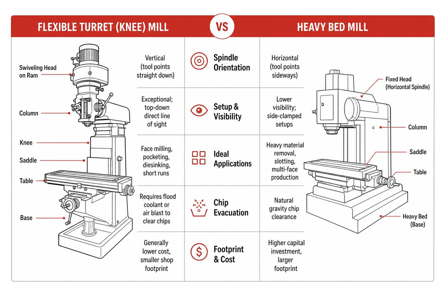
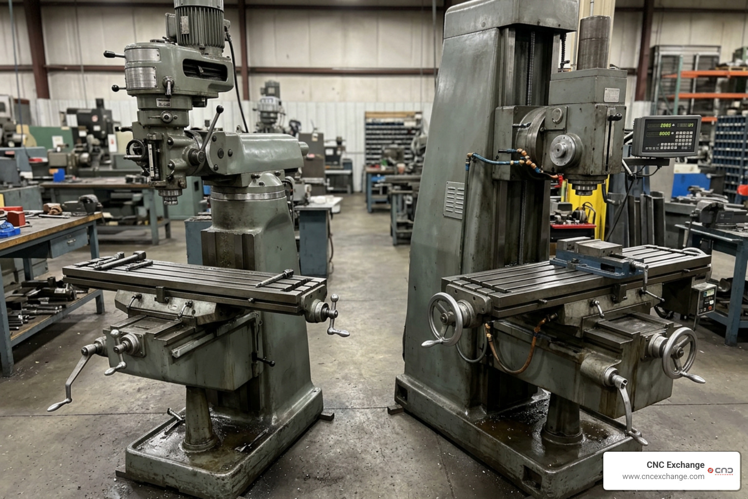
Turret vs Bed Designs in a Vertical Milling Machine
The two primary mechanical layouts are the turret mill (often called a knee mill) and the bed mill:
- Turret (Knee) Mills: The spindle remains stationary in X and Y while the work table moves beneath it. The swiveling head sits on a sliding ram that can extend or rotate over the table. This flexible layout makes turret mills highly versatile for toolrooms and light repairs, though the open joint structure slightly trades off maximum cutting rigidity.
- Bed Mills: The work table rests directly on a heavy bed and moves only in the X and Y directions. Vertical movement (Z-axis) occurs exclusively as the massive spindle column moves up and down. This rigid arrangement provides superior vibration damping, making bed mills ideal for heavy stock removal on massive forgings.
CNC Vertical Machining Centers (VMCs)
When computerized controls were integrated with vertical mills, the modern Vertical Machining Center (VMC) was born. VMCs feature fully enclosed work areas, high-speed automated tool changers (ATCs), automated chip conveyors, and high-pressure flood coolant delivery systems.
High-end VMCs like the NVX 5080 2nd Generation incorporate hybrid slideway structures, spindle thermal growth compensation sensors, and massive workpiece load capacities up to 2,205 lbs.
Modern VMCs also easily integrate 4th-axis rotary indexers or 5-axis trunnion tables, allowing shops to machine complex aerospace geometries on multiple part faces in a single setup. For specialized contract jobs, shops frequently utilize 4 Axis CNC Vertical Milling Services to manufacture multi-sided components efficiently.
Tooling Standards, Cutting Operations, and Toolpath Strategies
To translate spindle power into accurate surface finishes, a vertical milling machine relies on standardized tooling systems and structured cutting strategies.
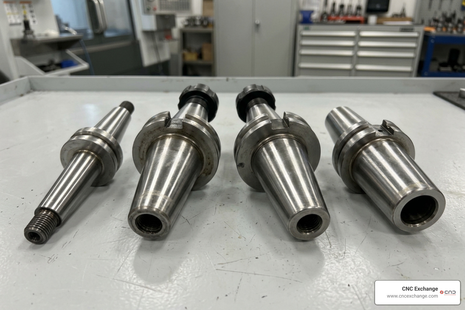
Toolholder Tapers: R8, CAT, BT, and HSK
Toolholder tapers connect the machine spindle to the cutting tool. Selecting the right taper depends on speed and cutting loads:
- R8 Taper: The standard drawbar-driven taper found on manual Bridgeport-style knee mills.
- CAT Taper: Developed originally by Caterpillar Inc. to standardize shop tooling. Uses an asymmetric pull-stud drive flange with imperial threads, common across American manufacturing facilities.
- BT Taper: Standardized in Asia and Europe, featuring a symmetrical drive flange that maintains excellent rotational balance at high RPMs.
- HSK Taper: A hollow-shank German standard designed for modern high-speed CNC machining. As the spindle rotates faster, centrifugal forces expand the internal collet mechanism, pulling the tool tightly against the spindle face for maximum rigidity.
Common Milling Operations: Face, Peripheral, and Pocket Milling
Vertical mills execute three primary material-removal operations:
- Face Milling: Cuts wide flat surfaces on top of the workpiece using indexable carbide insert cutters.
- Peripheral Milling (Side Milling): Uses the side flutes of an end mill to carve vertical walls, step features, or complex outer profiles.
- Pocket Milling: Clears internal material bounded by closed walls.
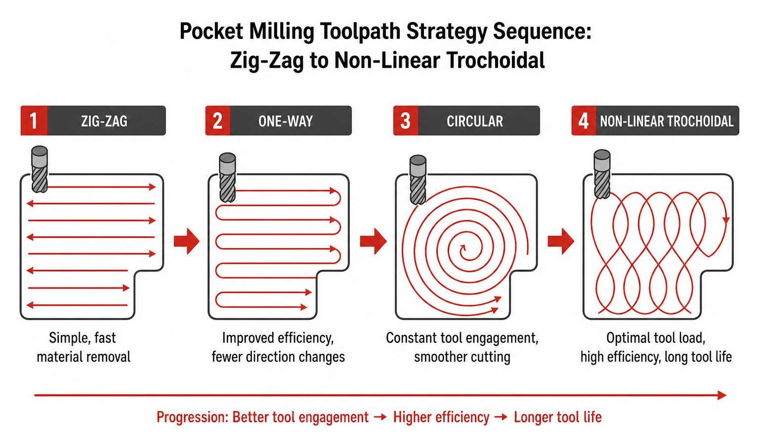
2.5-axis CNC pocketing strategies can easily machine up to 80% of all common mechanical parts. Machinists use zig-zag paths or non-linear trochoidal toolpaths to keep tool pressure constant while clearing deep cavities in metal alloys.
For secondary feature creation, engineers often route parts through specialized Heavy Industrial Tapping Machines or perform secondary operations directly on a vertical mill after initial lathe turning.
Machine Selection, Safety Practices, and Care
Selecting the right machine tool requires matching part size, material toughness, and production batch expectations to the proper frame style.
Evaluating Work Envelope, Rigidity, and Tolerances
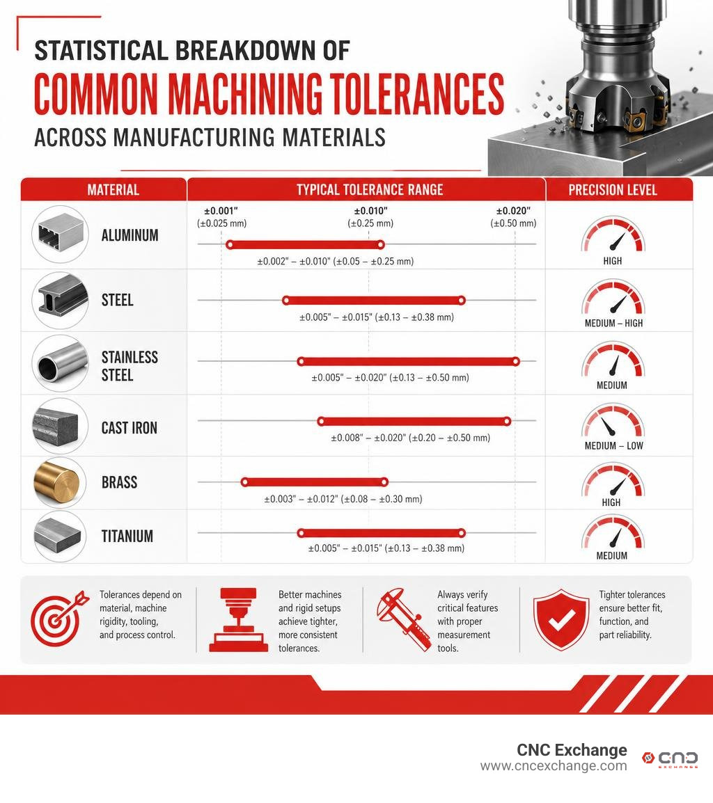
General machine shop tolerances for milling operations typically run around ±0.005" (~0.1mm) across standard metal geometries, with minimum wall thicknesses around 0.030" (~0.75mm).
When evaluating potential machinery, verify table dimensions and total stroke against the parts you manufacture:
- Light Precision & Mid-Sized Production: A versatile machine like the Haas VF-2 VMC or a Kitamura Mycenter-1 APC provides high spindle speeds paired with a modest footprint.
- Large Heavy Workpieces: Higher-capacity platforms like the Fadal VMC 6030 or Haas VF-5/40 handle heavy iron castings easily.
- Versatile Toolroom Work: Versatile options like the Southwestern Industries DPM V3 bridge the gap between manual flexibility and full CNC control.
Essential Maintenance for Your Vertical Milling Machine
To keep your machine accurate over decades of operation, perform these routine checks:
- Slideway Lubrication: Verify that the automated central oiler or manual one-shot lubricator pumps oil continuously to the way surfaces.
- Dovetail Wear Checks: Periodically check for central wear on manual knee mills by tightening table locks slightly and cranking handwheels to travel extremes to feel for binding.
- Acme Screw Backlash: Inspect and adjust feed screw backlash nuts to prevent tool grabbing during climb milling.
- Thermal Compensation: Allow modern CNC spindles to go through a warm-up cycle before cutting tight-tolerance work to equalize thermal growth across the machine structure.
Frequently Asked Questions
What is the main difference between vertical and horizontal milling?
The primary difference is spindle orientation. A vertical milling machine holds the cutter top-down, offering superior operator visibility and simpler workholding setups. A horizontal mill holds the tool sideways, enabling rapid chip clearance via gravity and fast multi-face machining using tombstone fixtures.
What tolerance levels can a vertical milling machine achieve?
Standard local precision for general milling ranges around ±0.005 inches (~0.1 mm) for metals. Modern precision CNC vertical machining centers with high-rigidity frames, glass scales, and spindle thermal growth sensors routinely maintain tight tolerances down to ±0.0002 inches (~0.005 mm) under controlled environmental conditions.
When should a shop upgrade from manual to CNC vertical milling?
A shop should upgrade to a CNC vertical milling machine when production runs expand past single prototype pieces into repeatable batches, or when parts require complex 3D surface contouring, multi-hole bolt circles, or high-speed pocketing that cannot be performed efficiently by hand.
Conclusion
The vertical milling machine remains an essential foundation of the modern machine shop. Its balance of direct visual control, versatile tooling configurations, and efficient workholding makes it the go-to tool for everything from simple job-shop modifications to multi-axis production runs.
If you are looking to scale up your shop's machining capacity or sell existing equipment to reinvest in higher-capacity CNC machining centers, visit our online platform to Browse CNC Exchange's Inventory of Vertical Machining Centers or Talk to Our Machine Tool Experts Today to unlock fair market value for your equipment.